How to Draw an Array in Autocad

Introduction to Polar Array in AutoCAD
Autocad is a computer-aided designing software which works on 2d and 3d engineering design. It was developed by the Auto desk. We can do a different type of drawing work in this software with the help of some 2d and 3d commands. In this article, we will discuss the Polar array, which is a 2d command through which we can distribute any particular object around a base point in 360 degrees and manage their rotation as well as number according to our requirement. So let us discuss the different types of features of this command and analyze its important parameters to better understand this topic.
How to use Polar Array in AutoCAD?
You can use a polar array in auto cad software in few simple steps by following its technique of use. We will understand this command with an example in this software, but before starting our learning, let us look at the working screen of this software to better understand this topic throughout this article.
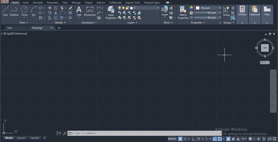
Step 1: At the top of the working screen, there is a ribbon which has the number of tabs such as Home tab, Insert tab, Annotate tab, View tab, and some other different tabs are there for handling important commands of this software, below this ribbon we have a working window in which we can see our current drawing working, this working window also have a navigation cube which helps us in change our view of drawing such as top view, front view, left view and some other isometric views, below this working window we have some navigation command for making our work easy in this software.
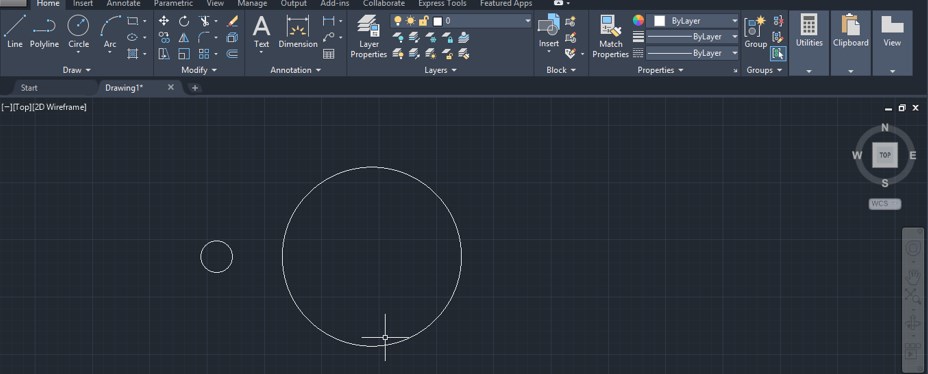
Step 2: Now, let us draw two circles one by one of the different radius with the help of a circle command like this to learn about polar array command. You can take any other shape for your learning according to you.
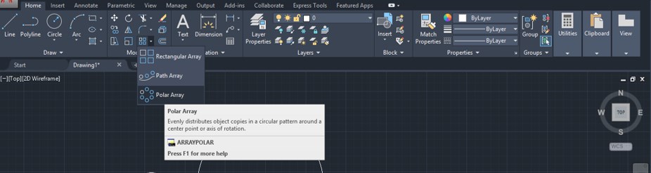
Step 3: Now, you can take the Polar Array command from the Modify menu of the Home tab of this software. For Polar array, go-to rectangular array command icon of Modify menu of Home tab of this software and click on the drop-down arrow of this icon then choose polar array command from the list by click on it.
Step 4: Or you can use a shortcut key for this command. For the shortcut key, press AR from the keyboard, then press enter button of the keyboard and your array command will be active.

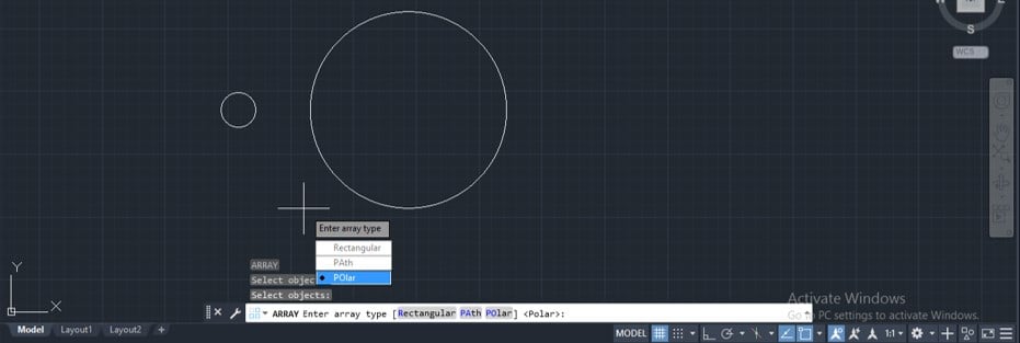
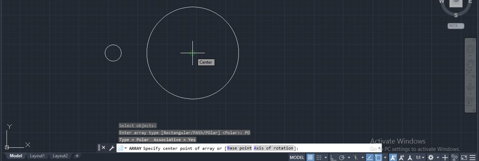
Step 5: Now it will ask you to select the object you want to distribute around this circle using the polar array command. So I will select this small circle by click on it with the mouse button.

Step 6: Now, if you use a shortcut key for this command, then it will ask you to choose the polar array command from this option so that I will click on the polar array option, or if you want to skip this step, then you can directly take polar array command from modify menu.
Step 7: Now, it will ask you to specify the point around which you want to distribute this small circle so I will choose the center point of this big circle as the center point of the polar array. You can choose any other point according to your drawing requirement.
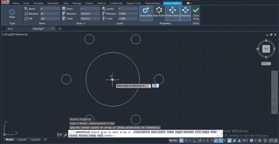
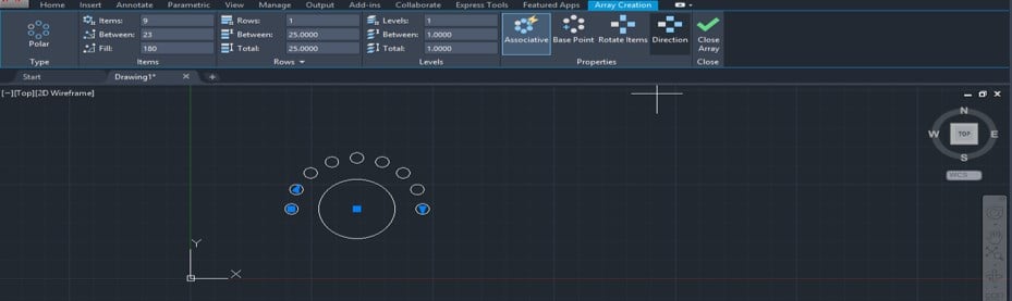
Step 8: Once you make a click at this center point of this circle, it will distribute your selected shape around the center point of this circle like this, and also an Array creation box will be open in commands section of this software for making changes in your applied array according to you.
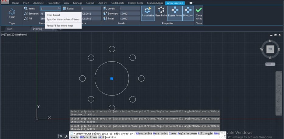
Step 9: Now, you can increase the number of array items by increasing the value of this Item option of the Array Creation tab. I will give 9 as the value of this option, and the number of items in my array will increase to 9 items.
Step 10: The angle between array items will adjust according to the number of items of the array and according to the fill angle of rotation of array.
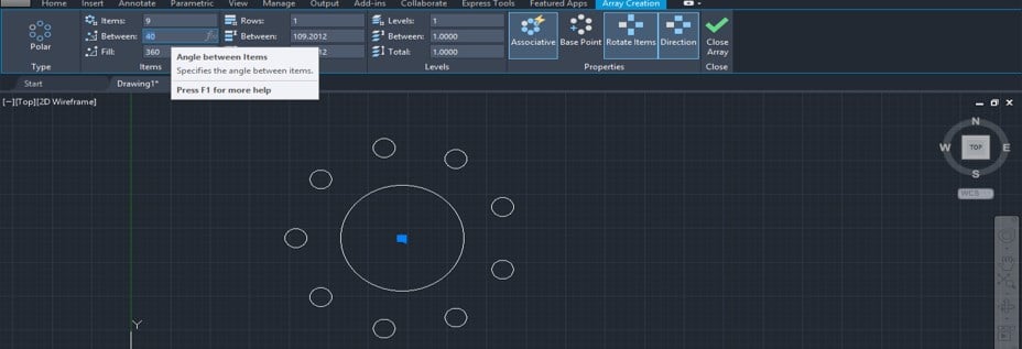
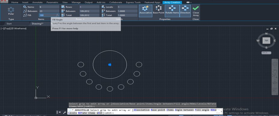
Step 11: You can change the value of the fill angle between 0 to 360 degrees. For example, if I will take 180 degrees as fill angle, then my array items will array only in 180 degrees around this circle.
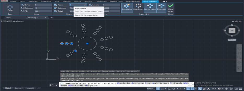
Step 12: You can increase the number of rows of array items by increasing the value of this row option of the Array creation tab. I will enter 3 as its value then my array item will distribute in 3 rows like this.
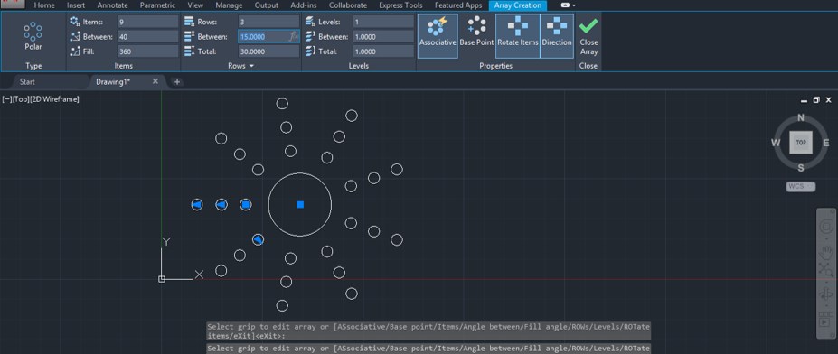
Step 13: You can also adjust the distance between rows by adjusting the value of this option such as I will give 15 as the distance between rows then my item will adjust at 15 distance in rows.
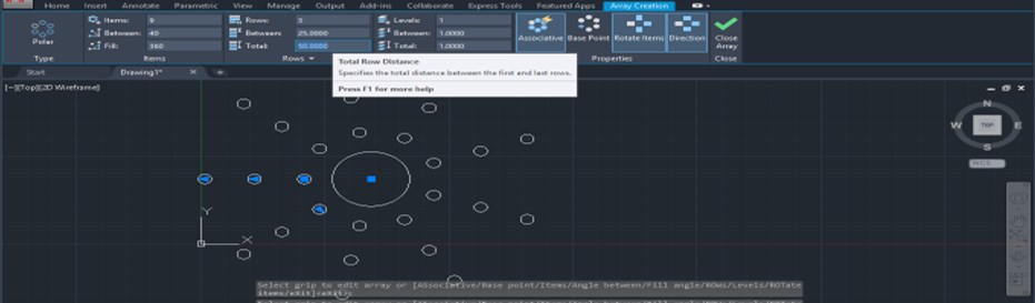
Step 14: By Total option, you can specify the length of rows such as I will give 50 as the value of total option then the length of rows of my item will increase to 50, and it will adjust the distance between rows in the same ratio.
Step 15: You can give the direction of array item if they are distributed at less than 360 degrees from the Direction option of this Array Creation tab. For example, I distributed my array item at 180 degrees around this circle and click on this direction option; then, the array item will start from this direction.
Step 16: You can increase the number of columns also of array item for the Levels option. For example, I increase the value of the levels option as 3 and increase the spacing between levels as 10. Now when you orbit this array, you can see 3 levels in the array of the array items.

You can edit the array after drawing it by selecting it again. In this way, you can use the polar array command in auto cad and use it for making a good drawing in auto cad. Using this command, you can also save your time of drawing the same item again and again.
Conclusion
Now after this article, you can understand what polar command is in auto cad and how you can handle its important features for getting the best result in your work. You can handle parameters of this command very easily by practicing on this command again and again.
Recommended Articles
This is a guide to Polar Array in AutoCAD. Here we discuss the Introduction, how to use Polar Array in AutoCAD and how you can handle its important features for getting the best result in your work. You can also go through our other related articles to learn more –
- AutoCAD Fillet
- Chamfer in AutoCAD
- Spline in AutoCAD
- AutoCAD PressPull
Source: https://www.educba.com/polar-array-in-autocad/
Post a Comment for "How to Draw an Array in Autocad"